In today's society, ground water detector has become an important tool for geological survey and groundwater resource management. However, how to operate and use ground water detector correctly is still a problem that needs to be understood. In this paper, we will introduce in detail the operation process and usage of ground water detector.

I. Operation Process
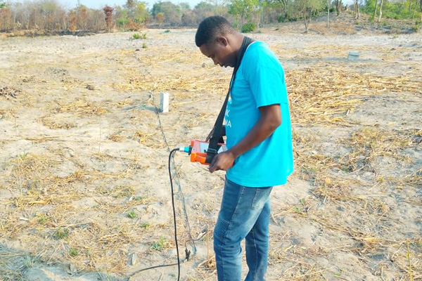
1. Wiring. Before measurement, it is necessary to carry out straight line wiring. According to the selected number of measurement points, place the cable and electrode rod in the area to be measured. Keep the electrode rod and cable line in good contact and the electrode grounded normally. For example, when 10 measurement points are to be measured, 14 electrode rods need to be placed. The host collects data from the center points of the M and N poles, the center points of M1 and N1 are the first measurement point P1, i.e., the position of the third electrode rod, the center points of M2 and N2 are the second measurement point P2, i.e., the position of the fourth electrode rod, and so on. Up to 18 points can be measured synchronously at one time.
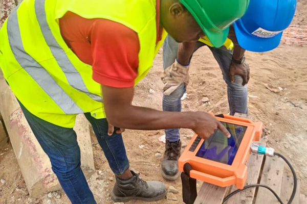
2. Parameter setting. Parameter setting is a crucial step in the operation of ground water detector. First, check whether the line is normal. Long press the line detection light, observe the line indicator at the bottom of the screen, all the indicator lights are on means the line is normal. Secondly, click "Profile" and then click "Measurement Parameter Setting" and "Line Number Setting". Each measurement of a place must be replaced with a measurement line number, such as the first line measurement, measurement of the next line you have to change the measurement line 1 into a measurement line 2, and then change the place to change the measurement line 3, and so on. Step 3: Points setting, according to the actual number of connected electrode rods minus 4 is the actual number of measurement points, such as only 20 electrode rods inserted, the actual number of measurement points is 20-4 = 16 points. Step 4: Depth setting, click depth, adjust to the corresponding depth you need to measure. (The increment and point number in the ground water detector interface generally do not need to be set, and the gain is normally defaulted to 0.)
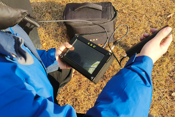
3. Start measurement. After completing the above steps, click OK, and then click Collect to start collecting data. At this time, there is a blue progress bar at the bottom of the screen display, and a beep to indicate the completion of data collection. Separately click on the screen curve, profile, 3D map and auxiliary analysis, you can view the desired results according to the actual situation of the map and analyze the measurement results on site.
4. Re-measurement method. When we finish the measurement of a line, in order to verify the authenticity of the data and the extension and scale of the structural abnormality, we usually re-measure a parallel line 5 meters away from the side of the original measurement line, and compare the results of the two measurements to confirm whether the measurement results are real and whether the data collection is valid. Through the curve diagram and profile, combined with the measured data and stratigraphic lithology and other comprehensive analysis of the geological structure of the situation, analyze the existence of water storage structures and conditions to determine the location of the well.
Precautions for use
1. Before using ground water detector for measurement, make sure the equipment is well grounded to prevent the equipment from being electrically charged, which may damage the equipment or cause injury to personnel.
2. When setting parameters, be sure to correctly select the line number and depth of the measurement, otherwise it will affect the measurement results.
3. In the re-measurement must pay attention to the parallel line distance should not be less than 5 meters to avoid affecting the measurement results.
4. In the profile measurement must ensure that the cable and electrode rod connected to a good or will affect the measurement results.
5. Keep the equipment clean and dry in the process of use to avoid dust and water vapor into the equipment to affect the normal operation and service life of the equipment.


