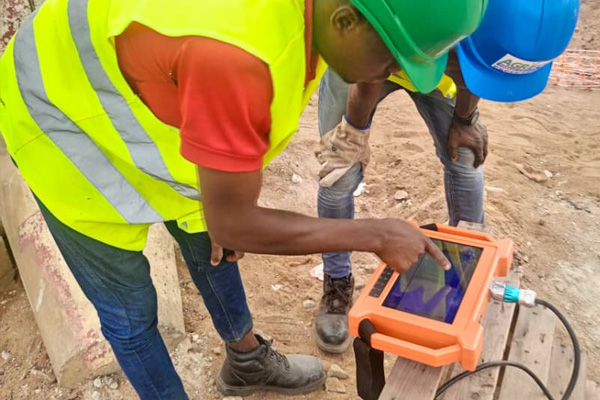
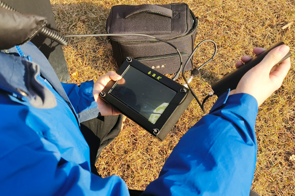
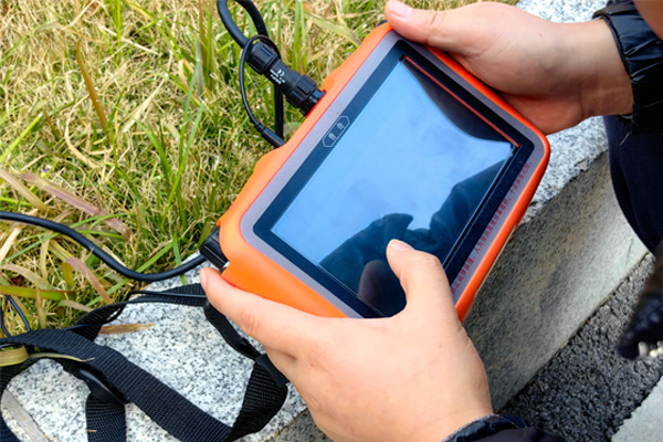
Ground water detector is an efficient groundwater detection tool that utilizes the principles of geological electrical exploration to infer the location and depth of aquifers by measuring the differences in electrical conductivity of underground rocks. To ensure accurate and efficient use of the ground water detector, the following are some key usage tips.
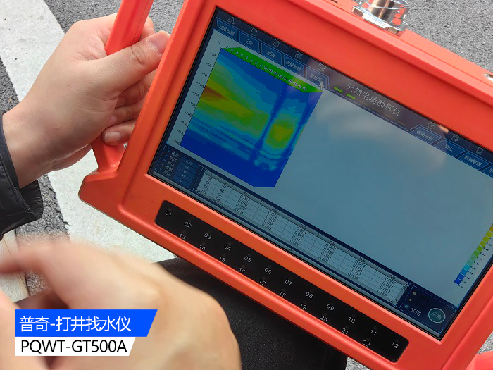
1、 Preliminary preparation
1. Wiring:
Before conducting on-site measurements, arrange cables and electrode rods reasonably in the area to be measured based on the selected measurement points.
1.2 Keep the electrode rod and cable in good contact to ensure that the electrode is properly grounded.
1.3 For example, when measuring 18 measurement points, it is usually necessary to place 22 electrode rods (the host collects data from the center points of the M and N poles, with each pair of electrode rods forming one measurement point).
2. Equipment inspection:
2.1 Check whether the equipment is intact, especially whether the cables and electrode rods are damaged.
2.2. Ensure that the equipment is well grounded to prevent damage or personal injury caused by live equipment.
2、 Parameter settings
1. Line detection:
Before starting the measurement, long press the line detection light and observe the line indicator lights below the screen to ensure that all indicator lights are on, indicating that the line is normal.
2. Measurement parameter settings:
2.1 Click on the "Profile" option, then click on "Measurement Parameter Settings" and "Line Number Settings" in sequence.
2.2 The measurement line number must be changed for each location being measured. If the first line is measured, the measurement line number must be changed from 1 to 2 when measuring the next line, and so on.
2.3. Point setting: Calculate the actual measurement points by subtracting 4 from the actual number of connected electrode rods (for example, if 22 electrode rods are inserted, the actual measurement points will be 18).
2.4 Depth setting: Adjust according to the actual depth to be measured.
3、 Measurement operation
1. Data collection:
After completing the parameter settings, click OK, and then click "Collect" to start collecting data.
1.2 A blue progress bar will be displayed at the bottom of the screen, and a beep will sound to indicate that the collection is complete.
2. Results viewing and analysis:
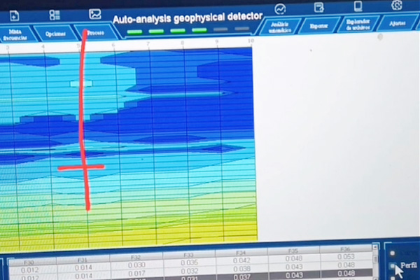
After the collection is completed, you can click on the curve chart, profile chart, 3D chart, and auxiliary analysis on the screen to view the measurement results.
2.2 Based on the actual situation and geological information such as lithology, comprehensively analyze the geological structure, determine whether there are water storage structures and conditions, and thus determine the well location.
4、 Retesting and Verification
1. Retesting method:
To verify the authenticity of the data and the extension and scale of the structural anomalies, a parallel line is usually re measured 5 meters away from the original survey line.
1.2 Compare the two measurement results to confirm whether the measurement results are true and whether the data collection is effective.
2. Comprehensive analysis:
2.1 Conduct comprehensive analysis by combining curve and profile diagrams with measurement data and geological lithology information.
2.2 Pay attention to observing abnormal changes, such as color anomalies, sudden changes in contour density, jagged, broken, V-shaped, or inverted V-shaped shapes.
5、 Precautions
1. Interference processing:
During the measurement process, there may be interference from point sources such as transformers and signal towers. At this point, a circular or semi-circular profile can be used for measurement, with the interfering object as the center and the radius of the circle set according to the size of the interference source, away from the interference source for measurement.
2. Color and numerical interpretation:
The colors and values in the section diagram indirectly reflect the differences in rock conductivity. The closer it is to red, the poorer the conductivity, and the closer it is to blue, the better the conductivity.
2.2 The conductivity of rocks is influenced by various factors, such as rock hardness, water quality, content of conductive minerals, and fracture rate. Therefore, it is not enough to judge the presence of water solely based on color, but rather requires a comprehensive analysis of numerical and geological information.
3. Exception recognition:
3.1 When analyzing profile maps, attention should be paid to identifying abnormal changes, including abnormal changes in color and contour lines. These abnormal changes may indicate the location or depth of the aquifer.
4. Safe operation:
4.1 When using a ground water detector for measurement, it is necessary to ensure that the equipment is well grounded to prevent damage or personal injury caused by live equipment.
During wiring, parameter setting, and measurement operations, safety operating procedures should be followed to ensure personal and equipment safety.
Mastering the skills of using a ground water detector is crucial for accurately and efficiently detecting groundwater. By reasonable wiring, accurate parameter settings, standardized measurement operations, and meticulous retesting and verification, the success rate and accuracy of water finding can be greatly improved. At the same time, it is necessary to conduct comprehensive analysis and judgment based on geological information and professional knowledge to ensure that the final determined well location can meet actual needs.


